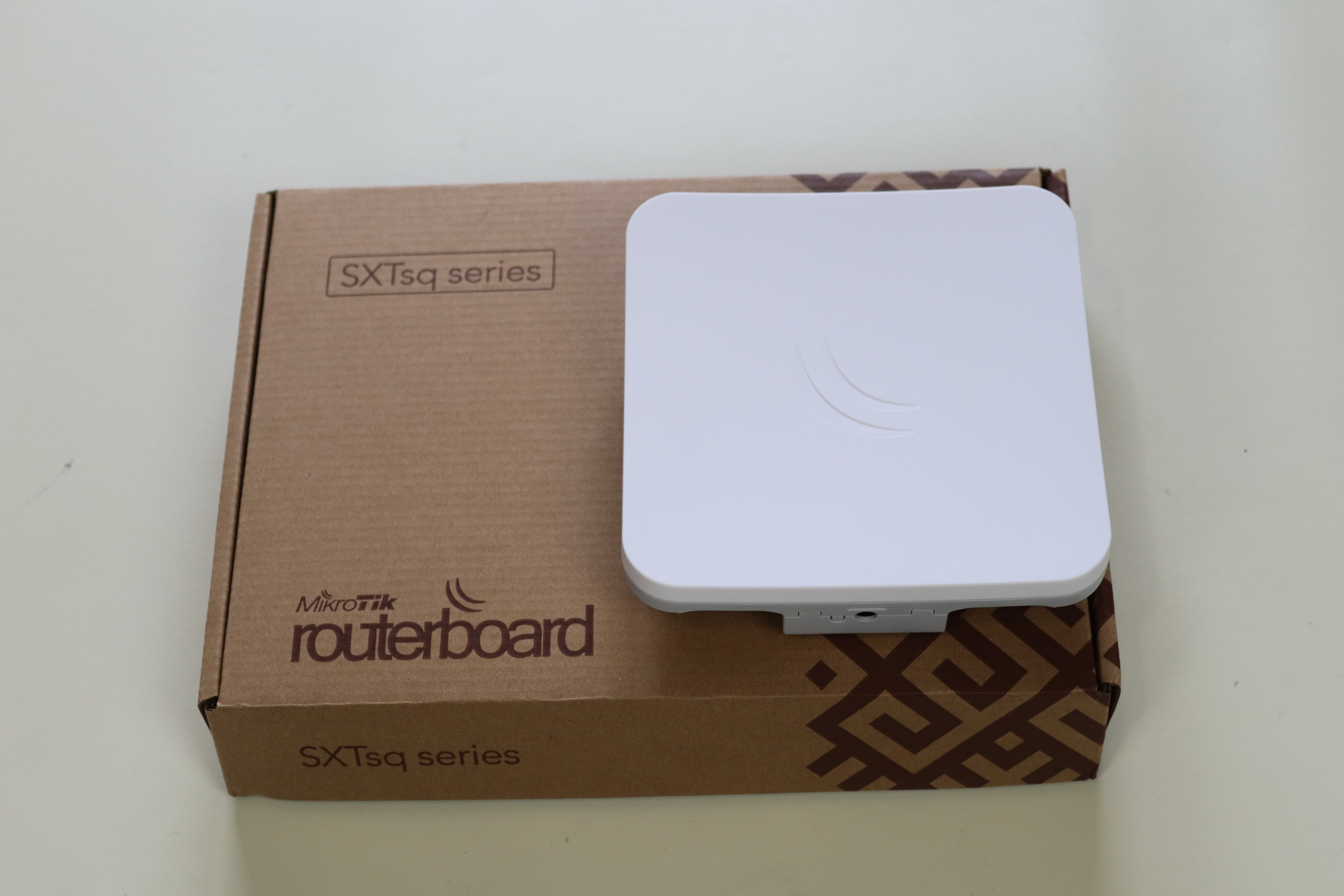
Today I used a pair of Mikrotik SXTsq 5 ac devices to establish a transparent wireless PTP (point to point) link.
This project is part of a larger project to connect a few buildings together and load balance a few different links so I made the subnet small; however if you just want to extend layer 2 that can just as easily be done.
I did run into a licensing issue that I didn’t really plan for. These devices come with a level 3 Router OS license; level 3 licences don’t allow you to use this as a wireless AP. You’ll get an error along the lines of, “Couldn’t change Interface <wlan1> – license does not allow AP mode”.

This isn’t a huge deal though; at the moment I’m only using this as a PTP bridge and although I planned on one day adding my chicken coop into the mix and making this a PTMP setup I’ll just have to adjust at that time.
AP mode supports multiple clients (PTMP) while Bridge mode only supports 1 client (PTP). The clients here being the other radio/s.
The Project

The overall link physical topology can be seen above.
Here is how I set up the PTPs you will setup both sides the same; except, Step 4 and the IP address will differ:

Out of the box these devices come with a default config that hands out DHCP on the ETH port; so don’t plug it in and forget about it like I did.
- Login via winbox.
Default credentials:
user: admin
password: (its blank)
2. Remove the default configuration.

3. Enable wlan1 by selecting wlan1 and hitting the blue check mark


4. I recommend the following settings:
- Mode: One side will be bridge and the other station bridge
- Band: 5GHz A/N/AC
- Wireless Protocol : nv2
- Default Authenticate: Checked

5. Setup NV2 check security and add a Preshared key. It must be the same on each end.

6. Create a bridge

7. Add interfaces ether1 and wlan1 to the bridge. Notice here wlan1 is showing as disabled? STP had shut it off because both devices were plugged into the same switch port while I was setting them up.
8. Set your IP addresses; I didn’t show it here but I do prefer to assign the IP to the bridge itself rather than to a physical interface. That way if the physical interface the IP belongs to goes down and the other interface is still up you are still able to get to the device.

9. Apply all of your settings and test the wireless link between the two. Remember STP will shut down interface if there is a loop. I ended up taking a bridge to the other room and just powering it via the provided power injector.
By default the signal lights correspond to the following values
- Lowest 1 (1 LED on) -91 dBm
- 2 LEDs on -81 dBm
- 3 LEDs on -71 dBm
- 4 LEDs on -61 dBm
- 5 LEDs on -51 dBm
10. You should be ready to mount your PTPs now!
Below I have posted a few other pictures I took of the radios. Pictured is the QuickMount Pro by Mikrotik. While it is cool I don’t really think it was necessary to purchase this; the default mounting hardware that comes with the radio would have been sufficient for me.


