Table of Contents
T1 lines are a standard in telecommunications, providing high-speed digital transmission of voice and data. These lines are often used to connect different telecommunications equipment, such as routers, PBX systems, or network interface units. When setting up a direct connection between two T1 devices (such as two routers or a PBX and a router), a T1 crossover cable is typically required. This article will explain what a T1 crossover cable is, why it’s needed, and how to create one.
What is a T1 Crossover Cable?
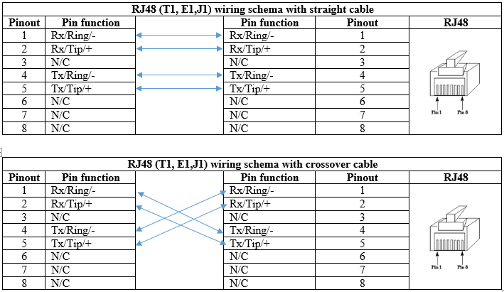
A T1 crossover cable is a specific type of twisted-pair cable that is wired to connect two T1 devices directly. Unlike a standard straight-through cable, where the transmit (TX) pins on one end connect directly to the corresponding TX pins on the other, a crossover cable swaps the transmit and receive (RX) pairs. This allows the two T1 devices to communicate directly with each other, ensuring that the transmit signals from one device are properly received by the other.
Why is a T1 Crossover Cable Needed?
In typical T1 setups, a straight-through cable connects a T1 device (like a PBX or router) to a service provider’s network interface. However, when connecting two similar devices directly, such as two routers or a PBX and a router, both devices are configured as DTE (Data Terminal Equipment) and will attempt to transmit data on the same pins. A crossover cable is necessary to swap the transmit and receive pairs, enabling proper communication between the two devices.
T1 Crossover Cable Pinout
The wiring for a T1 crossover cable differs from that of a standard Ethernet or PRI crossover cable. T1 typically uses RJ-48C connectors, which are similar in appearance to RJ-45 connectors but are wired differently. Below is the specific pinout required for a T1 crossover cable.
T1 Crossover Cable Pinout Table
The table below shows how the pins should be connected for a standard T1 crossover cable using an RJ-48C connector.
| Pin | Function | Pin on Device 1 | Pin on Device 2 |
|---|---|---|---|
| 1 | Transmit + (TX+) | 1 | 4 |
| 2 | Transmit – (TX-) | 2 | 5 |
| 4 | Receive + (RX+) | 4 | 1 |
| 5 | Receive – (RX-) | 5 | 2 |
| 3, 6, 7, 8 | Unused | – | – |
Standard Cable Colors for T1 Crossover Cable
When creating a T1 crossover cable, it’s essential to follow the standard color codes for twisted-pair cabling. Below is the typical color code scheme for T1 cables.
| Pin | Color for Pin on Device 1 | Color for Pin on Device 2 |
|---|---|---|
| 1 | White/Blue | White/Orange |
| 2 | Blue/White | Orange/White |
| 4 | White/Orange | White/Blue |
| 5 | Orange/White | Blue/White |
Tools Required
To create a T1 crossover cable, you will need the following tools:
- RJ-48C Connectors: Two RJ-48C connectors for each end of the cable.
- Twisted-Pair Cable: Cat5e or Cat6 cable is typically used for T1 lines.
- Crimping Tool: For securing the RJ-48C connectors to the cable.
- Cable Tester: To ensure the cable is wired correctly and functions as expected.
How to Create a T1 Crossover Cable
Creating a T1 crossover cable involves carefully arranging the wire pairs to match the crossover pinout. Below is a step-by-step guide.
Step-by-Step Guide to Creating a T1 Crossover Cable
- Cut the Cable: Measure and cut the twisted-pair cable to the desired length.
- Strip the Cable Ends: Use a cable stripper to remove about 1 inch (2.5 cm) of the outer jacket from both ends of the cable, exposing the individual wires.
- Arrange the Wires: Untwist the pairs and arrange the wires according to the crossover pinout for each end.
- For Device 1, arrange the wires in the following order: White/Blue, Blue/White, White/Green, White/Orange, Orange/White, Green/White, White/Brown, Brown/White.
- For Device 2, arrange the wires in the following order: White/Orange, Orange/White, White/Green, White/Blue, Blue/White, Green/White, White/Brown, Brown/White.
- Insert the Wires into the RJ-48C Connector: Carefully insert the arranged wires into the RJ-48C connector, ensuring they stay in the correct order.
- Crimp the Connector: Use the crimping tool to secure the RJ-48C connector to the cable.
- Repeat for the Other End: Follow the same process to attach the second RJ-48C connector to the other end of the cable, using the corresponding pinout.
- Test the Cable: Use a cable tester to check the continuity and ensure the cable is wired correctly.
Testing and Verification
After creating the T1 crossover cable, it’s crucial to test it before deploying it in your network. Use a cable tester to verify the following:
- Continuity: Ensure that each pin is connected correctly from one end to the other, as per the crossover pinout.
- No Shorts: Check for any shorts or miswiring, which could prevent the devices from communicating correctly.
Common Applications for T1 Crossover Cables
T1 crossover cables are commonly used in the following scenarios:
- Connecting Two Routers: Directly connecting two routers in a back-to-back configuration for testing or redundancy purposes.
- PBX to Router Connections: Connecting a PBX system directly to a router when bypassing a T1 network interface device.
- Lab Testing: Creating test setups in lab environments to simulate T1 connections between different devices.
Conclusion
A T1 crossover cable is a specialized cable essential for connecting two T1 devices directly, ensuring proper communication by swapping the transmit and receive pairs. Understanding the correct pinout and color coding is crucial when creating a T1 crossover cable to avoid connection issues.
By following this guide, you can confidently create and test a T1 crossover cable, ensuring reliable and efficient communication between your T1 devices. Whether you’re setting up a new connection or troubleshooting an existing one, having the knowledge to create and use a T1 crossover cable is an invaluable skill in the field of telecommunications.

